Dynamic unbalance, what is it?

It's all about centrifugal force


centrifugal force, graphiccentrifugal force, graphiccentrifugal force, graphic, rpm dependency

Centrifugal force is an outward force which exists in rotating bodies


F = mω²r
ω = Δθ/Δt (angular speed)

Centrifugal force is proportional to the distance between mass and rotational axis

Centrifugal force is proportional to the square of rotational speed

Why can some Balancing Systems measure unbalance without actually spinning the part? What determines the need for a “spin balancer”?


Drum-shaped rotating body, masses in same plane

rotor drum with unbalance in center plane

The answer is in the shape of the rotating part:

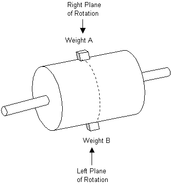
In this picture, both mass A and mass B are located in the same plane of rotation. Centrifugal forces generated by both masses are acting in the same plane of rotation.
Because of this, the combination of both masses acts as if it were indeed combined in one mass.

The result:
Static unbalance


Drum-shaped rotating body, masses in different planes

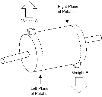
rotor drum with unbalance in left and right planes

In this picture, mass A is located at the far left. This plane is called "Left plane of Rotation"
Mass B is located at the far right side of the drum-shaped body. This plane is called "Right plane of rotation"
Centrifugal forces generated by both masses are acting in different planes of rotation.
Because of this, each mass will try to pull the drum in the direction of it's centrifugal force.

The result:
Dynamic unbalance


Balancing tooling, balance fixture

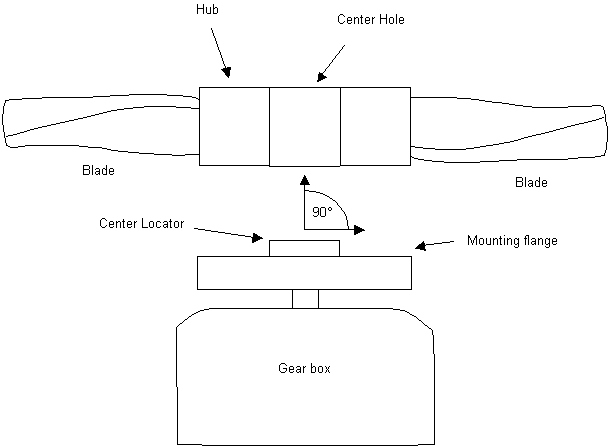
propeller mounting on gear box

The interface between balancing machine and rotating part is fundamentally important. The interface is called tooling, or fixture. Tooling errors will falsify the unbalance measurement, regardless of the accuracy of the measuring system.


The Tooling or balancing fixture has to be able to mount the part at it's true center AND perpendicular to the shaft, repeatably and accurately.


Eccentricity and perpendicularity

balancing machine tooling, eccentricity error

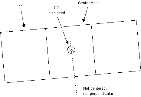
Mounting errors in eccentricity and perpendicularity move the CG of the part (Center of Gravity) away from the axis of rotation, thereby introducing unbalance (which is the same as mass eccentricity). The displacement of the CG causes balance measurement errors.

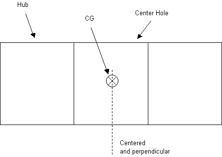
When the fan hub is mounted in the exact center and perpendicular to the shaft, the CG of the fan is in line with the axis of rotation:

When the fan hub is mounted in the exact center and perpendicular to the shaft, the CG of the fan is in line with the axis of rotation:


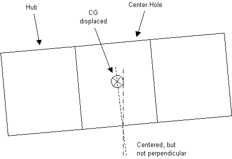
balancing machine tooling, perpendicularity error

A slight tilting of the fan causes the CG to move away from the axis of rotation


balancing machine tooling, perpendicularity and eccentricity error

When tilt  and eccentricity are combined, the CG displacement is even greater