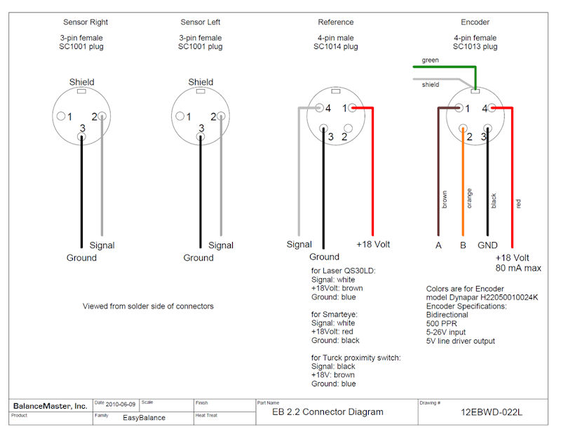
Connectors:
Sensor Right and Sensor Left: Switchcraft A3F
Reference sensor (photocell or proximity switch: Switchcraft A4M
Encoder: Switchcraft A4F
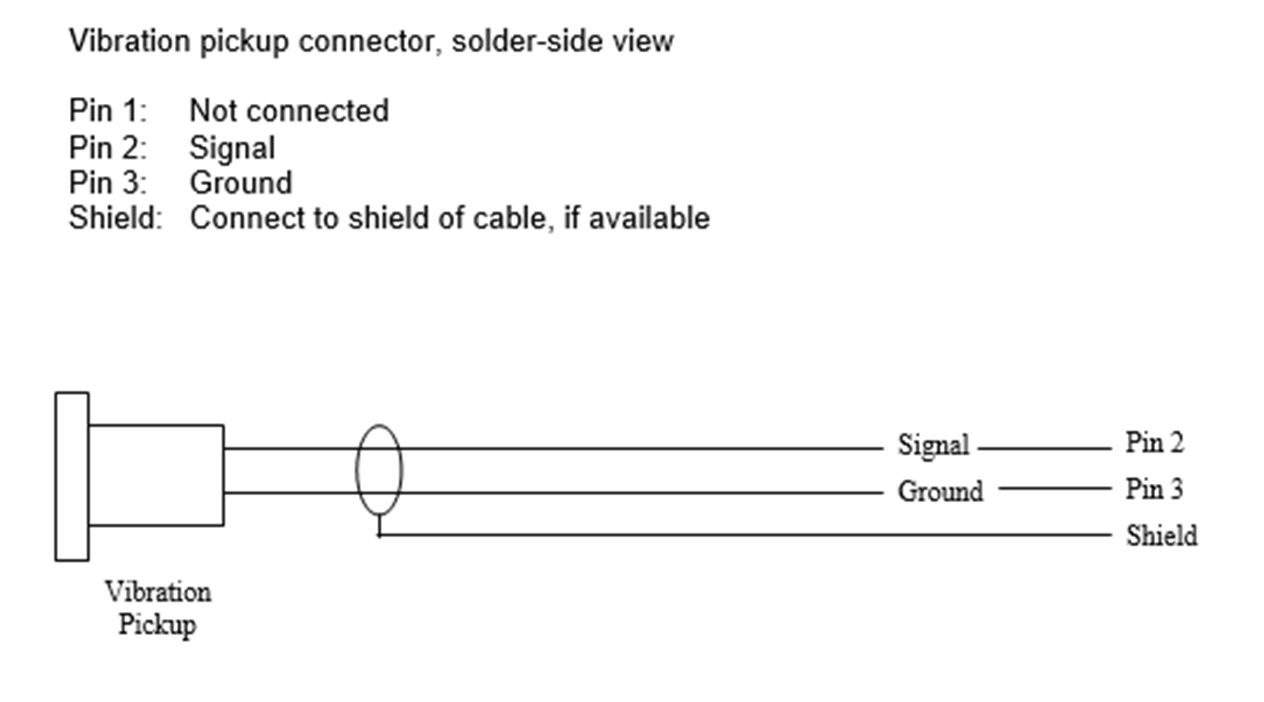
Vibration connector details
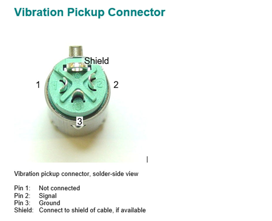
Connector: Switchcraft A3F
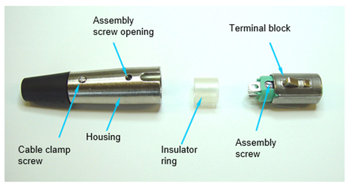
To open the connector, insert a small screw driver into the
assembly screw opening and turn the screw CCW. Pull out terminal block,
insert cable trough housing and through insulator ring.
Solder the cable to the terminal block.
Re-assemble connector and tighten assembly screw CW. Tighten cable clamp screws (2).